
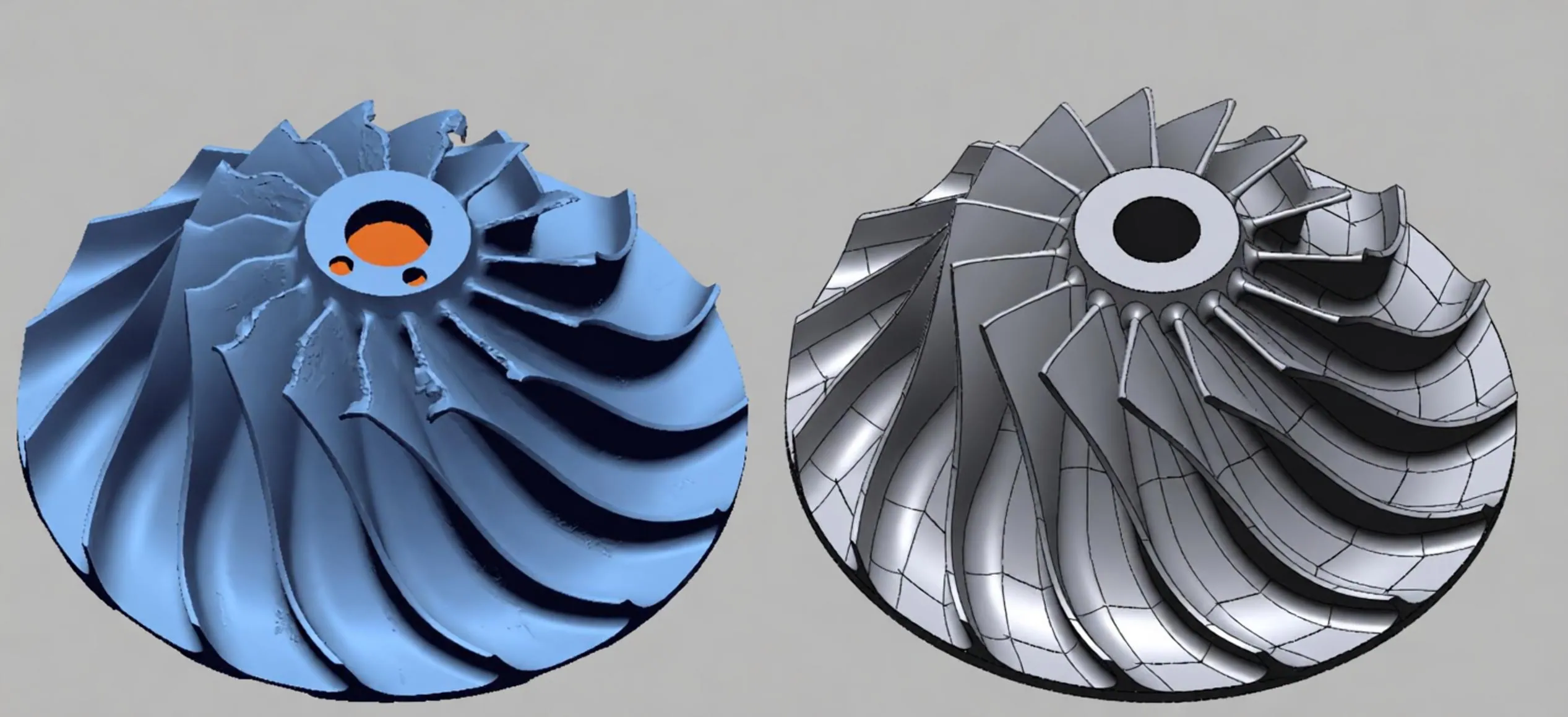
Centrifugal compressor impellers are critical components in oil & gas, power generation, and industrial refrigeration. When an impeller is obsolete, damaged, or undocumented, reverse engineering is the only path to a functional replacement. This guide covers the complete workflow: 3D scanning, wear compensation, parametric CAD reconstruction, CMM validation, CNC machining, and dynamic balancing.
Why Impeller Reverse Engineering Is Different
Impellers are not simple prismatic parts. They feature:
- Freeform blades with complex 3D curvature
- Tight tolerances on blade angles and hub fit
- Dynamic balancing requirements per the ISO 1940-1 balancing standard (G2.5 quality grade or better)
- High-speed rotation, requiring material integrity and surface finish control
Manual measurement cannot capture these features. 3D scanning and parametric CAD are essential.
The 6-Step Impeller Reverse Engineering Workflow
1
High-Density 3D Scanning
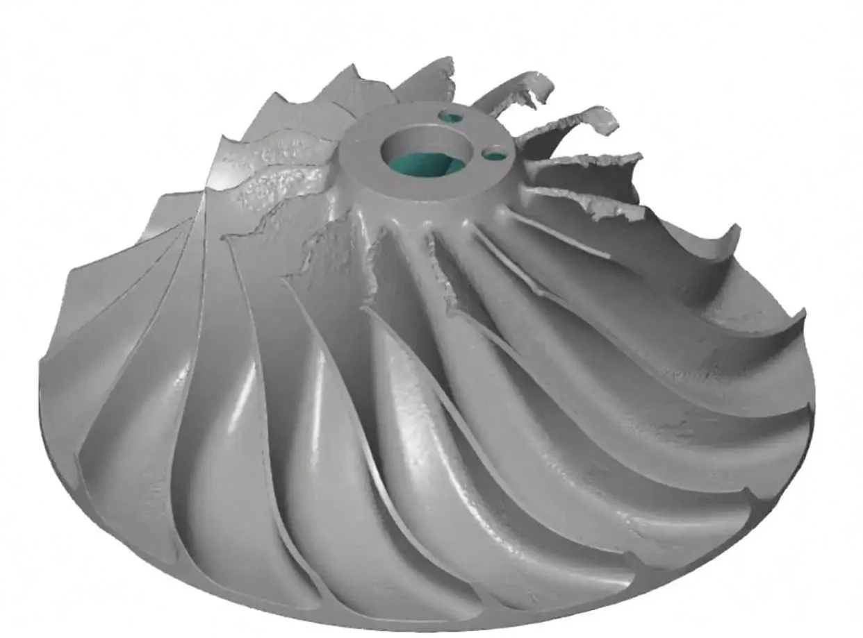
Capture the impeller, even if worn or damaged, using industrial blue-light 3D laser scanners.
- Volumetric accuracy: up to ±0.02 mm
- Blade feature verification: CMM down to ±0.005 mm
- Output: point cloud + STL mesh
2
Wear Compensation and Deviation Analysis
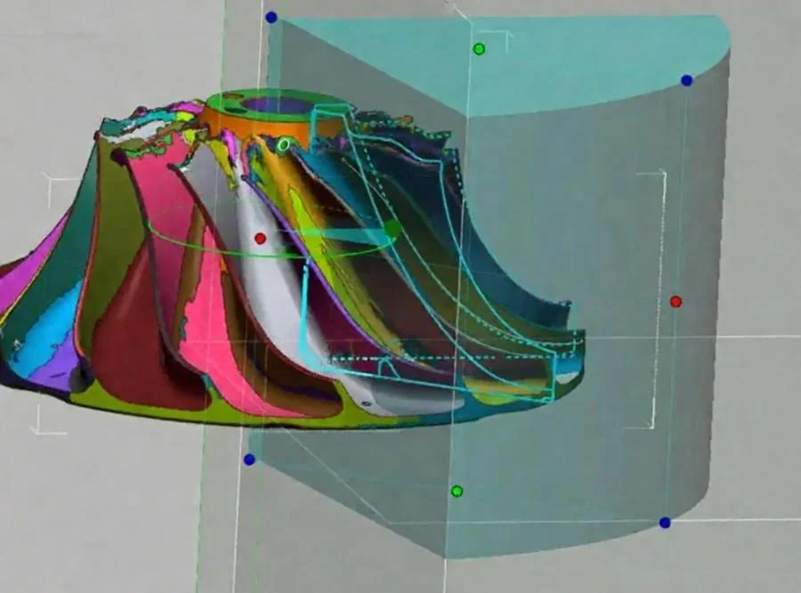
Distinguish service-induced wear from original geometry. Use deviation analysis (color mapping) to reconstruct nominal blade profiles.
3
Parametric CAD Reconstruction
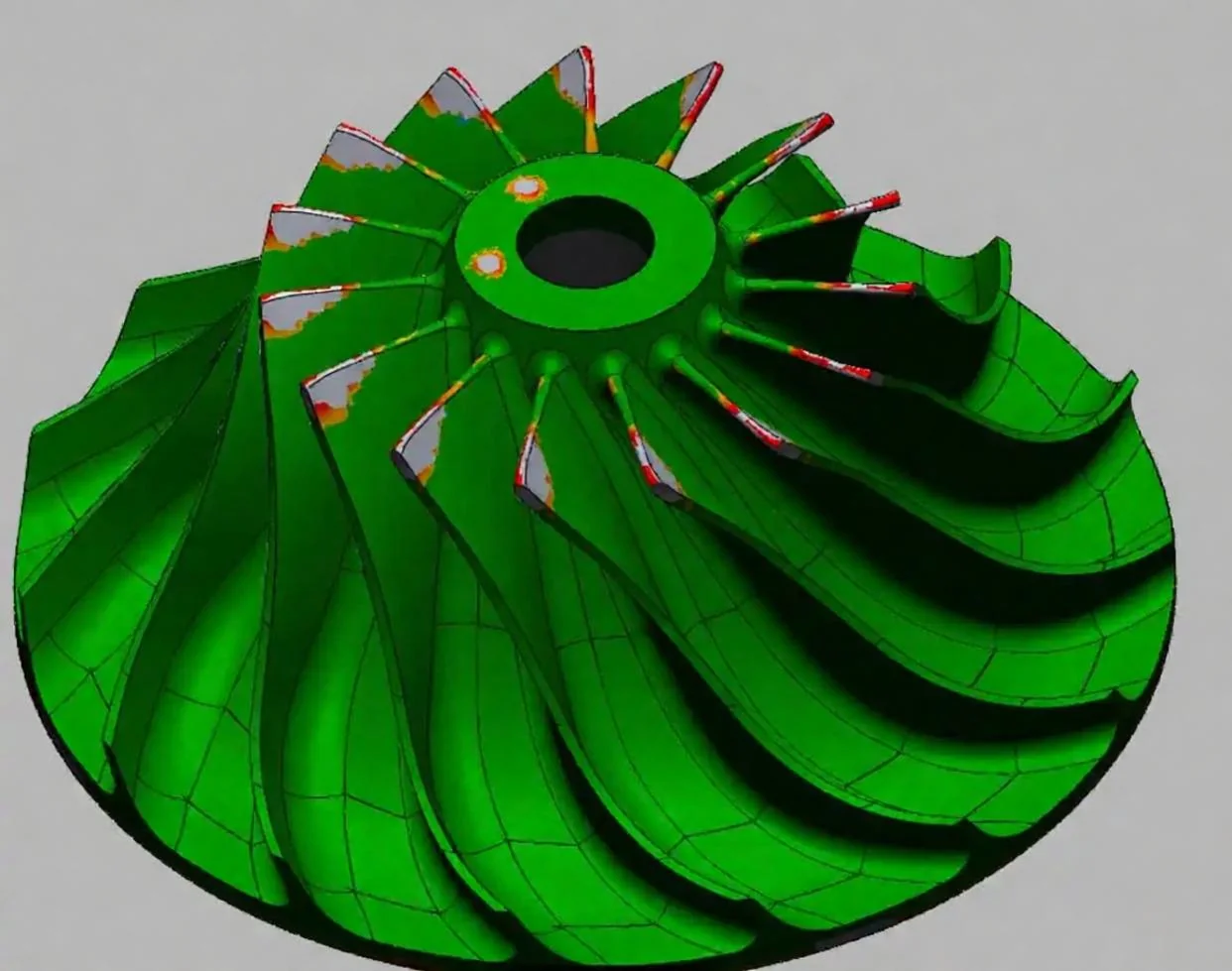
Rebuild a fully editable CAD model with proper blade surfaces, hub, and mounting features.
- Deliverables: SolidWorks (.sldprt), STEP, IGES, Parasolid (.x_t)
- GD&T per ASME Y14.5 / ISO 1101
4
CMM Inspection and Metrology Validation
Machine a first article and validate critical dimensions and blade profiles on a bridge-type CMM.
- Output: FAI report (AS9102 structure) + dimensional inspection
5
CNC Machining
Machine the impeller from aluminum, stainless steel, or titanium.
- Tolerances: Metals ±0.05 mm (ISO 2768-f)
- Surface finish: Ra 0.8 μm – Ra 3.2 μm
6
Dynamic Balancing
Perform dynamic balancing per ISO 1940 G2.5 or better. Provide balancing report.
Comparison: Mechonus Impeller Reverse Engineering vs. Traditional OEM Replacement
| Feature | Mechonus Reverse Engineering | Traditional OEM Replacement |
|---|---|---|
| Drawing Required | No. Physical sample is sufficient. | Yes. Requires OEM drawings. |
| Lead Time | 2–4 weeks (e.g., Ø100 mm impeller: ~1 wk scanning-to-CAD + ~1 wk machining + balancing) | 6–32 weeks |
| Wear Compensation | Yes. Restores nominal geometry. | Not applicable |
| CMM Validation | Included | Not always provided |
| Dynamic Balancing | Included (ISO 1940 G2.5) | Included (if OEM) |
| MOQ | 1–500 pieces | High MOQ |
| Documentation | CMM report + FAI (AS9102) + MTR + balancing report | OEM certificate only |
Industry Applications
- Oil & Gas: Compressor impellers for pipeline and refinery service
- Power Generation: Gas turbine and steam turbine impellers
- Industrial Refrigeration: Centrifugal compressor impellers
- Mining: Slurry pump impellers
See our compressor impeller reverse engineering case study for a real project example.
FAQ
Can you reverse engineer a compressor impeller without drawings?
Yes. We reverse engineer the impeller using 3D scanning and parametric CAD reconstruction, then CNC machine and dynamically balance the replacement. No original drawings are required.
How do you ensure the impeller is dynamically balanced?
We perform dynamic balancing per ISO 1940 G2.5 or better, and provide a balancing report with the final part.
What materials can you machine for impellers?
We machine aluminum (6061, 7075), stainless steel (304, 316, 17-4 PH), titanium (Ti-6Al-4V), and other alloys.
What is the typical lead time for an impeller reverse engineering project?
Standard lead time is 2–4 weeks from sample receipt to delivery, including 3D scanning, CAD reconstruction, CNC machining, and dynamic balancing. Expedited service is available.
Do you provide CMM inspection reports?
Yes. Every impeller project includes CMM dimensional inspection and a FAI report (AS9102 structure).
Conclusion
Centrifugal compressor impeller reverse engineering is a controlled engineering workflow, not a simple 3D scan. Mechonus delivers CMM-validated, dynamically balanced replacement impellers without OEM drawings. For related services, see our reverse engineering services and CNC machining services.